DHTML JavaScript Website Pull Down Navigation Menu By Milonic
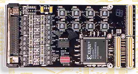
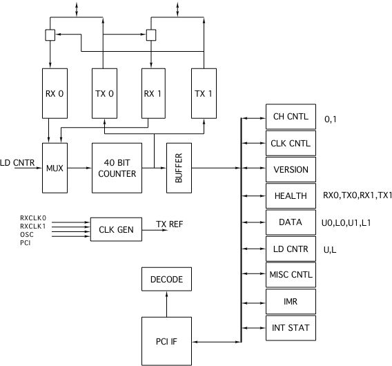
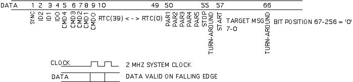
PMC-BiSerial-BAE1 PMC Compatible Real Time Clock Interface PMC-BiSerial-BAE1 Block Diagram PMC-BiSerial-BAE1 Timing
The PMC-BiSerial-BAE1 implements the BAE Real Time Clock protocol. This protocol uses a 40 bit clock representation to keep multiple processes within a system in synchronization. The BAE1 can be programmed to be the master or a target within the system.Please note that the PMC-BiSerial has been upgraded and the PMC-BiSerial-III is currently recommended for new designs estimates the RTC between updates from the master source. The software assigns an ID to the targets. All messages contain the RTC, and all messages which pass parity checking are used to update the local counter. If the ID and Command match, the local programmed values the target will respond to are the master with either the ID and Command [health check] or a pre-programmed message.BAE1 is programmed to be a master then the process is somewhat reversed. The local counter becomes the system master. The reference is selected to be the local oscillator. The clock is broadcast to the targets along with the RTC values. The master keeps the time and repeats the broadcast every 128 uS [with a 2 MHz reference]. If the Master wants to check on a target then a command is embedded into the start of the message with the Target ID and Command to send. The Target will append data to the end of the message with the ID/CMD repeated or new data depending on the system configuration.start bit which is set to 1. The next 8 bits are the ID [3] and Command[5]. 40 bits of RTC data follow. 5 parity bits which correspond to the 5 bytes of RTC data are next. The stop bit is 0. After the stop bit the master always releases the bus to allow the target to respond. If the master is not expecting a message then the message will be ignored. The sequence for the Target is turn-around, start = ´1´ 8 bits of data, turn-around, then the master resumes driving the bus. Each of the subgroups are transmitted MSB first. Parity is programmable. If your situation demands a custom application then we will update the Xilinx FPGA. Send us your timing and we will send you the interface....
email us your wish list or call today!
Order Information PMC-BiSerial-BAE1 PMC BiSerial with BAE1 interfacePMC-BIS-Eng-Kit1 ..........Engineering Kit options for PMC-BiSerial-BAE1 include Board level Schematics [PDF], Driver and Reference Software [Win32 driver, Visual C reference files], HDEterm68-MP, HDEcabl68PMC-BIS-Eng-Kit2 ...........Engineering Kit 1 plus PCI2PMC card. 68 position terminal strip to SCSI III connector adapter and BiSerial compatible SCSI III cable You must have Adobe Acrobat to read our PDF files. pmcbis_bae1_man_a2.pdf pmcbis_bae1_wdm_man.pdf Custom, IP, PMC, PC*MIP, PCI, VME Hardware, Software designed to your requirements Home |
News |
Search the Dynamic Engineering Site
[an error occurred while processing this directive]