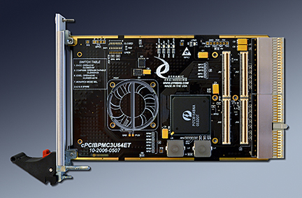
cPCIBPMC3U64ET
cPCI to PMC Compatible Adapter/Carrier, Front View


cPCIBPMC3U64ET is a 3U 4HP PMC adapter for cPCI. One PMC position is provided with a 32/64 bit interface for both the PMC and the cPCI backplane. User programmable VIO on the PMC side of the bridge. High capacity mini-planes with filtering for 3.3 and 5V.

A related product,, "cPCIBPMC6UET" is a 6U 4HP version with two PMC positions. The 6U version has both PMC IO connectors routed with equal length traces to J3 and J5. A PIM Carrier is available for the 6U model to support rear panel IO.

cPCIBPMC3U64ET ( cPCI to PMC ) adapter / carrier converter card provides the ability to install a PMC card into a standard cPCI slot. cPCIBPMC3U64ET has a PMC card slot mounted to a universal 3U 4HP cPCI card. Suitable for 32/64 with 33/ 66 MHz bus operation. The 3U card is wired for 64 bit PCI operation with pull-ups on the control lines to allow use in a 32 bit system. The PMC bezel connector is mounted though the cPCI mounting bracket. The cPCIBPMC3U64ET is an extended temperature design. -40C to +85C standard. Conformal Coating is an option.

The PCI bus is interconnected to the PMC via 64 bit 66 MHz capable layout. The slower and more narrow device will determine the interface characteristics.

PCI VIO is interconnected to the primary side of the bridge. The secondary side of the bridge has programmable VIO allowing 5V PMC´s to be used in 3V systems and vice-versa. The voltage select pins are not installed on cPCIBPMC3U64ET. The bridge will automatically adapt to the PCI bus reference voltage. Many PMC´s are "universal" and can work with 3.3 or 5V cPCI backplanes.

Power is routed from the cPCI to PMC connectors with mini-planes each of which is rated for more than the maximum PMC draw. 3.3, 5, VIO, +12, -12

cPCIBPMC3U64ET has a low internal power dissipation. The dissipation is a function of the frequency and load from the installed PMC´s. The bridge uses 1W at 66 MHz and less at 33 MHz. The terminations contribute additional dissipation for a total of less than 1.2W at 66 MHz with a 64 bit implementation. Please add your PMC requirements to the 1.2W figure for total power utilized in the slot.

With 3U cPCI, J2 has two definitions - in a 64 bit PCI implementation J2 has the upper A/D and control signals, and in a 32 bit PCI implementation J2 has the rear panel IO. cPCIBPMC3U64ET has the upper part of the PCI bus connected to J2. In addition the commonly used Ethernet and I2C pins from the Jn4 and Jn1 are optionally connected to unused [reserved] pins on J2 to allow rear panel IO for those signals. Please refer to the manual for the signal definitions.

If you have custom requirements please call or e-mail us with the details.


cPCIBPMC3U64ET Features

  • Size
  • 3U 4HP cPCI

  • PMC compatible slot
  • 1 PMC position provided.

  • Clocks
  • cPCI bus can operate at 66 or 33 MHz. The PMC must be 66 MHz capable for 66 MHz operation to work properly. User switch to allow or disable 66 MHz. operation.

  • Access Width
  • Standard cPCI byte lanes supported for byte, word and long access dependent on installed PMC. 64 or 32 bit operation supported.

  • Software Interface
  • PMC register definitions as defined by installed hardware. No software set-up required by cPCIBPMC.

  • Interrupts
  • INTA, B, C, D routed to cPCI connector from PMC.

  • Signal Conditioning
  • Secondary side PCI signals are routed and terminated IAW the PCI specification.

  • Power
  • +5, +3.3, +12, -12V, and VIO supplied to PMC.

  • VIO
  • Bridge primary PCI IO Voltage is set by the PCI backplane. Secondary side VIO is programmable by the user.

  • Thermal
  • cPCIBPMC3U64ET is a low power design with minimal heat dissipation for optimal PMC performance. Less than 1.2W used by bridge and terminations for 66 MHz. 64 bit implementation. 33/32 wil be lower. The temperature range is -40C to +85C

  • IO Interface
  • Front Bezel IO supported at cPCI bracket. Partial Jn4 "user IO" supported [Ethernet and I2C] with interconnection to J2.

  • LED´s
  • +3V, +5V, +12V, -12V and Busmode.

  • JTAG
  • optional JTAG header connected to PMC. JTAG pin definitions are in the silkscreen.

  • Volatility
  • Statement of Volatility


    cPCIBPMC3U64ET Benefits

  • Speed
  • The bridge allows for isolation and for differing clock rates on the cPCI backplane and the PMC.

  • Price
  • cPCIBPMC3U64ET represents a cost effective solution to putting extended temperature PMC´s into cPCI environments. Make use of existing PMC designs in cPCI applications without paying for the expense of a new design and layout. Quantity discounts are available.

  • Warranty
  • 1 year warranty

  • Ease of Use
  • cPCIBPMC3U64 is easy to use. A plug and play interface to the PMC site.

  • Availability
  • We attempt to keep cPCIBPMC3U64ET in stock. Send in your order and in most cases have your hardware the next day.

  • Size
  • cPCIBPMC3U64ET is a 3U 4HP cPCI board which conforms to the cPCI mechanical specifications. Eliminate mechanical interference issues. cPCIBPMC3U64ET can be used in all cPCI slots.

  • PMC Compatibility
  • cPCIBPMC3U64ET is PMC compliant per the IEEE 1386 specification. All Dynamic Engineering PMC Modules are compatible with cPCIBPMC3U64ET.

  • cPCI Compatibility
  • cPCIBPMC3U64ET is cPCI compliant.


    cPCIBPMC3U64ET Ordering Options

  • cPCIBPMC3U64ET: extended Temperature cPCIBPMC3U64ET J2 installed upper PCI bus and partial IO [Ethernet and I2C], IO through Bezel (front panel).

  • -VIO3: The VIO3 option forces the secondary VIO to be 3.3V only: no mistakes about voltage selection

  • -CC: Add conformal coating option

  • -FAN[HV][R]: Add a fan. Standard orientation is to blow onto PMC. Add "R" to fan callout to reverse air flow. Zero Slot fans have approximately 5 CFM. For an 8 CFM fan add the "-HV" designation. Please note: HV fans are mounted on the rear and will interfere with the next slot.
    Examples:
    -FAN adds fan in the standard orientation - air toward PMC
    -FANR adds fan in reverse orientation, air pulled from PMC
    -FANHV is mounted on the rear, and blows toward the PMC
    -FANHVR is mounted on the rear, and pulls from the PMC

    Using the drop down menus, select your board build options and add on options.

    Quantity


    Manual
    You must have Adobe Acrobat to read PDF files

    Download the
    cPCIBPMC3U64ET Manual rev B1 in PDF format.


    Dynamic Engineering's Hardware and Software design overview


    Try before you buy program


    Custom, IP, PMC, XMC, PCIe, PCI, cPCI, PC104p, PCIe104, VME, VPX Hardware, Software designed to your requirements


    Home | News | Search the Dynamic Engineering Site