Made in USA
The Embedded Solutions Experts
PC104p-Chassis
Chassis for PCIe104, PCI-104, PC104p, and PC104 card stacks
CLICK ON PHOTOS FOR LARGER VIEWS

PC104p-Chassis Description
- Heavy Duty Chassis suitable for PC104, PC104p, PCI-104, and PCIe104 applications
- Integrated Heat Sink
- Water Tight design with gasket
- standard and custom lengths
- Finish options including: bare metal, anodized, hard anodized, Chem Film (MIL-DTL-5541 Type II), etc.
- Custom modifications
- 1 year warranty standard. Extended warranty available.
Dynamic Engineering has updated the PC104p-Chassis design. Improvements include a larger heatsink while retaining the same maximum height and width to be compatible with previous revision implementations. Suitable for PC104, PC104p, PCI-104, and PCIe104 applications.
The chassis incorporates an extruded aluminum outer housing with machined end caps. The interface between the End Cap and Chassis includes a gasket to support water tight operation at low pressures. The End caps are suitable for the addition of your connectors. The chassis is rugged and can work in a variety of environments.
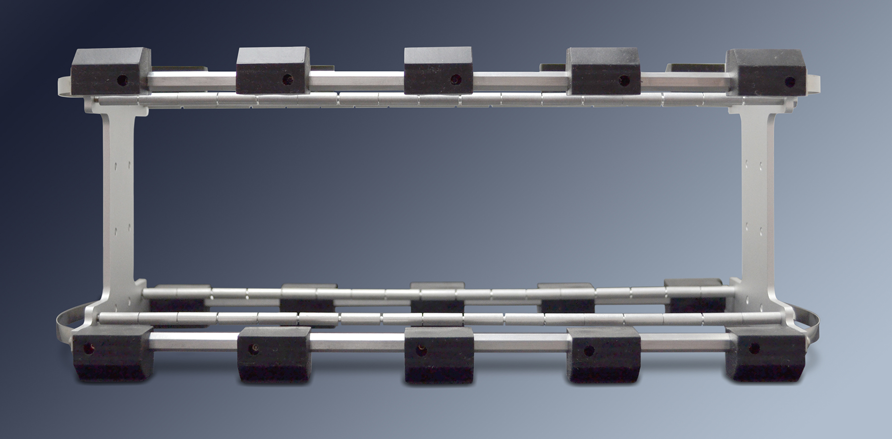
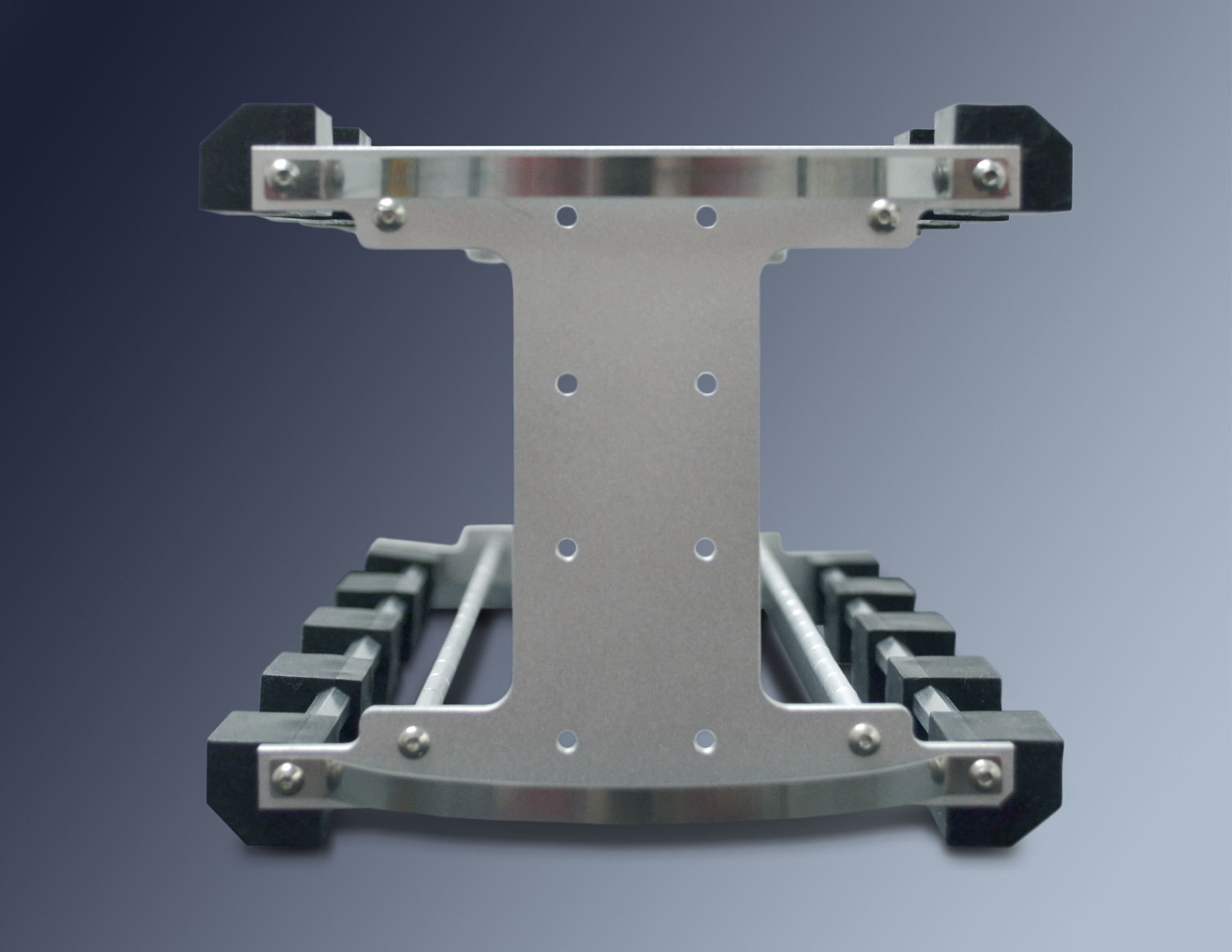
The internal card cage is isolated with "bumper pads" from the external housing to provide vibration and shock absorption.
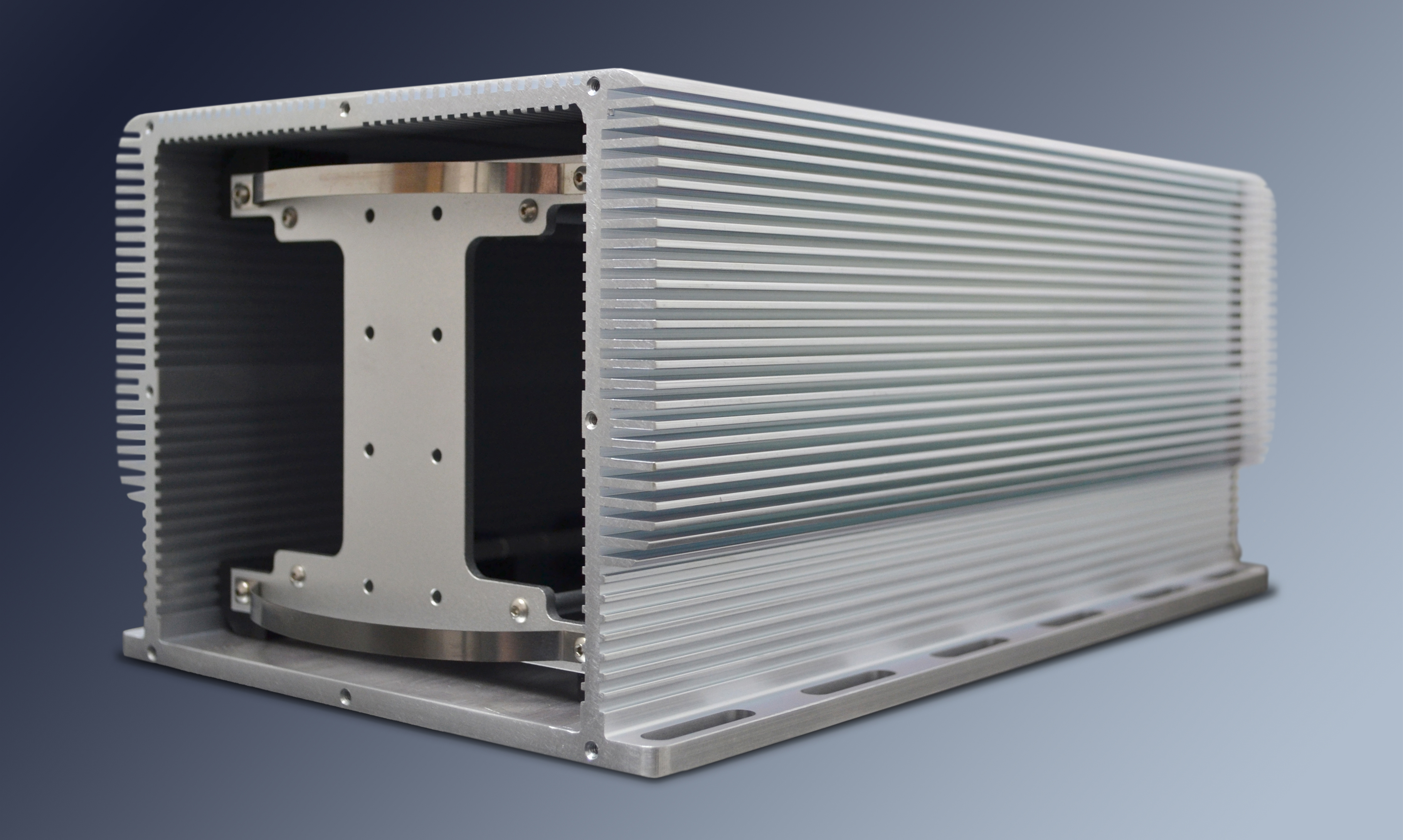
The chassis features heat sinks built into the external and internal walls. The current version has expanded heat sinks with larger wider fins compared to the original design. The internal heat sink has the added benefit of helping the internal chassis slide into position. The bottom surface is extended to create a mounting flange which can also be used for cooling in conductively cooled systems. The heat sink is tapered to provide access to the mounting flange. The heat sink is rounded to help avoid sharp edges.
Standard and custom lengths, power supplies, Fan boards, Reverse Power Protection, custom machining, surface finish, and etching or silk screening are available options. The shelf system is available to allow for mounting multiple SSD and/or other non-Stack HW to your system. In addition, a single slot SSD specific mounting adapter is available.
The PCIe104, PCI-104, PC104p, PC104 Chassis comes in base sizes : 1-11 where the size refers to the number of stack elements available. [an extrusion is used for the main body of the chassis making any length up to 24 in. possible]. The models are adaptable to allow any number of slots to be used up to the maximum for the chassis length. For example, if you need extra room for long connectors, or bend radiius on stiff cabling order a longer chassis coupled with a shorter internal frame. For example, an 11 slot chassis with a 9 position internal card cage. For custom combinations please contact Dynamic Engineering.
In a typical system the first position in the stack is the power supply, the second the CPU and the rest IO or storage. With the range of cards available for PCI-104, PC104, PC104p and IP available most applications can be implemented with off-the-shelf hardware and a chassis. a href="PC104p-PWR28.html"> PC104PWR28 can make a good power supply for PCI-104, PC104 and PC104p stacks or stacks with mixed cards. The 28V refers to aircraft 28V power. This supply has a wide range of input voltage and regulated protected outputs. The chassis is flexible and works with any assortment of cards.
To use the chassis: First, build your stack with standard spacers etc. Second attach to the rear plate with spacers and screws. Third add spacers to the front side to fill in the unused positions and attach to the internal cage front bezel. Attach shelving system if in use. Four screws and 4 nuts for the stack plus 4 more screws for the side supports. "rapid assembly!" We can provide additional assembly and test services to install the power supply, CPU, IO etc. shipping a completed unit to you.
Click on play to see videos for disassembly/reassembly of the inner chassis and outer chassis. Click the box for full screen. ESC returns to standard page. Click the download button to watch on your local machine - use when your internet bandwidth is too low to properly support the video.
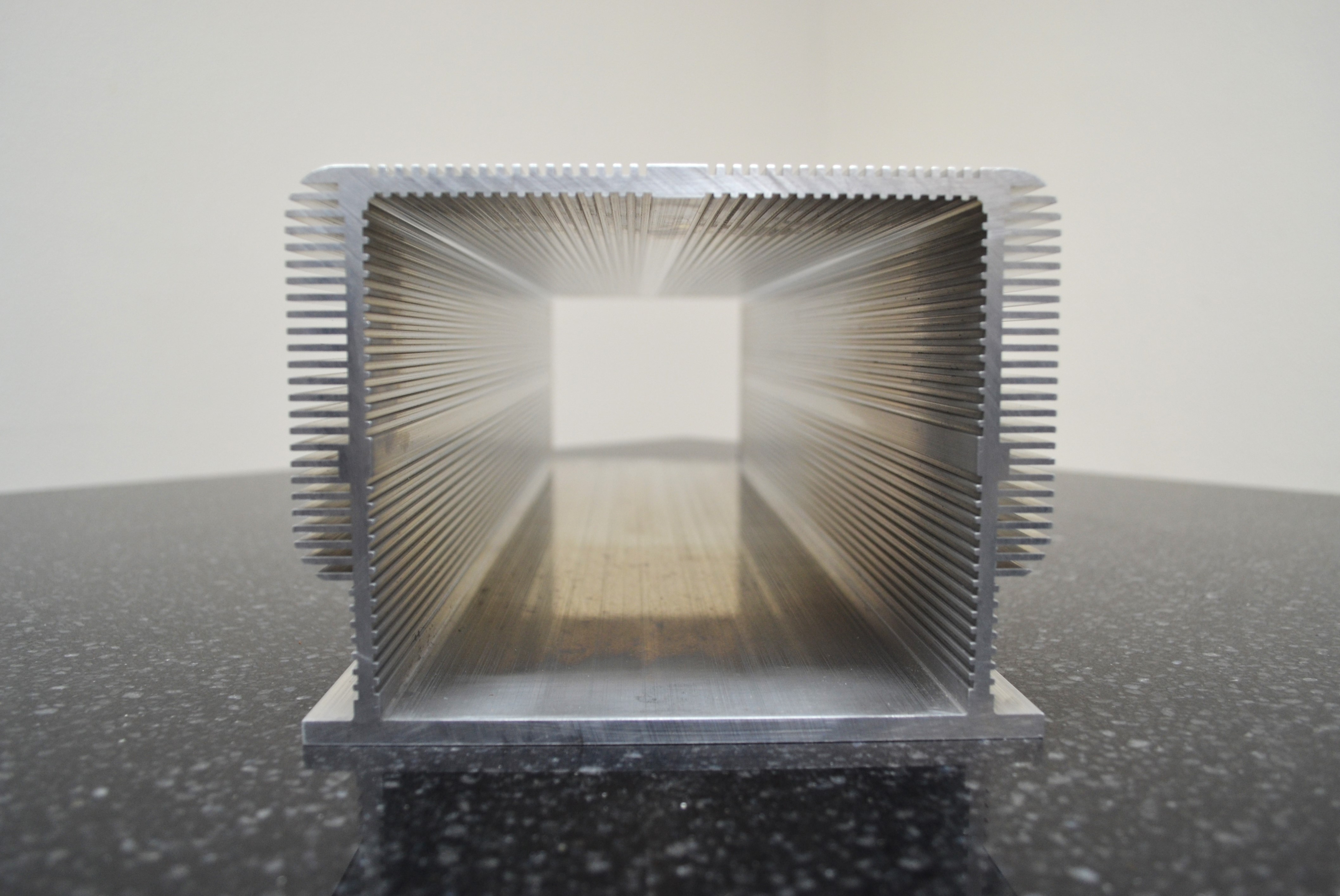
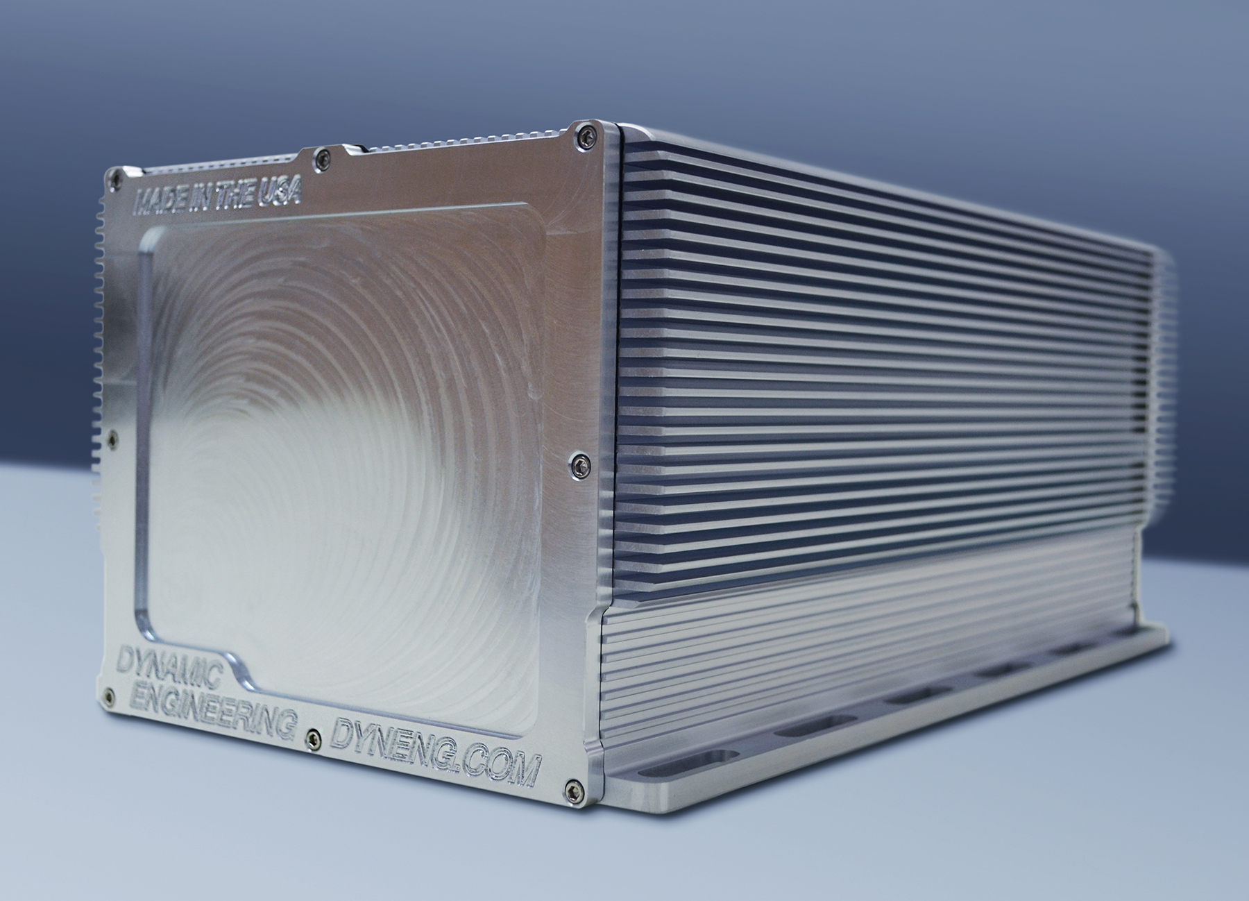
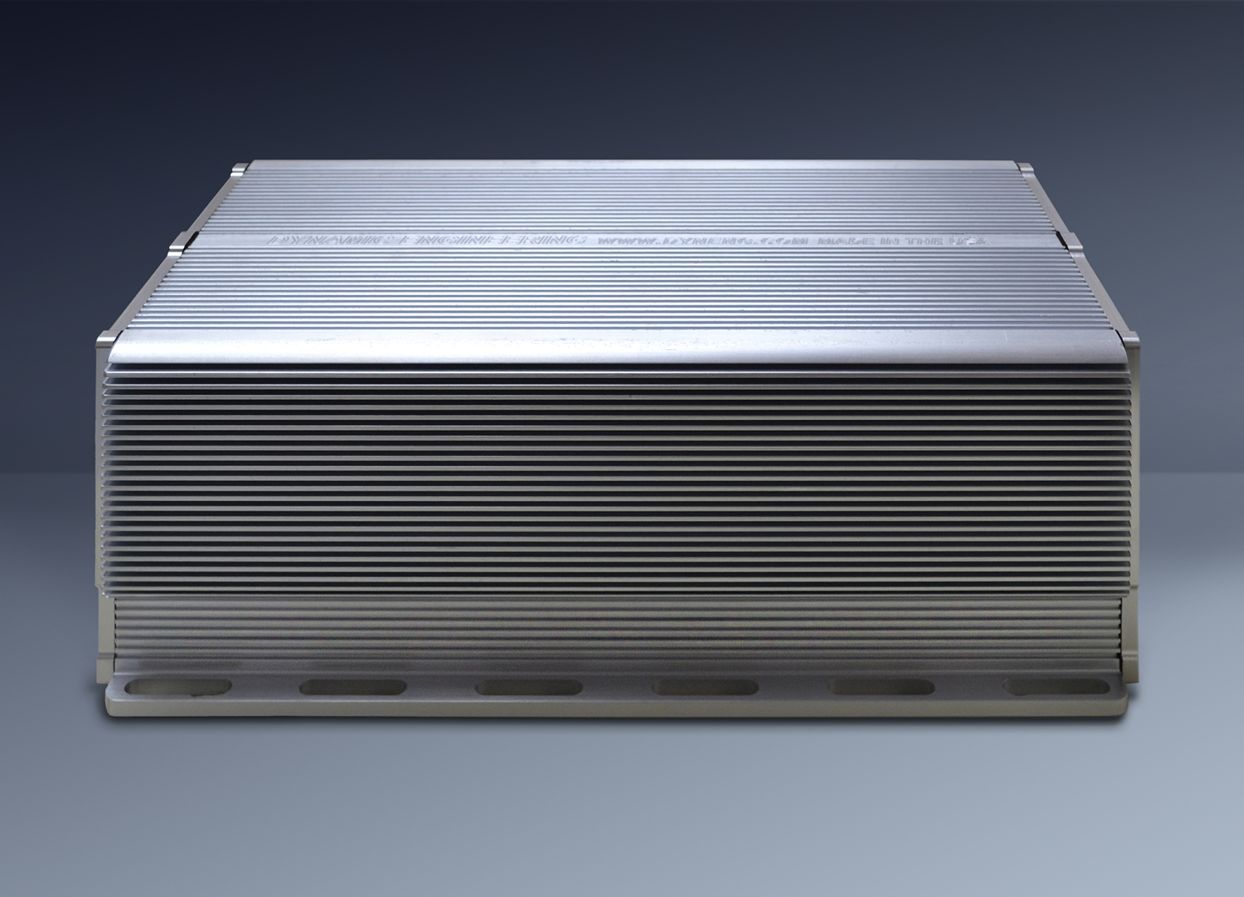
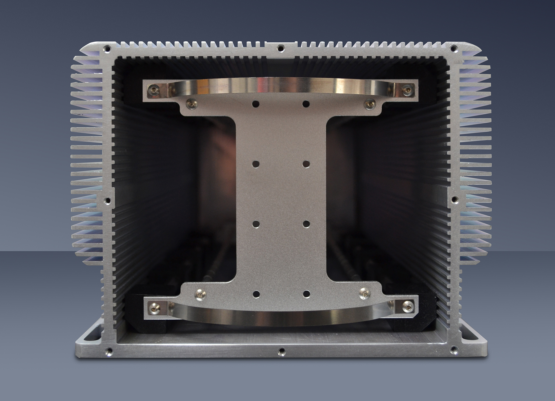
Side View of Chassis.
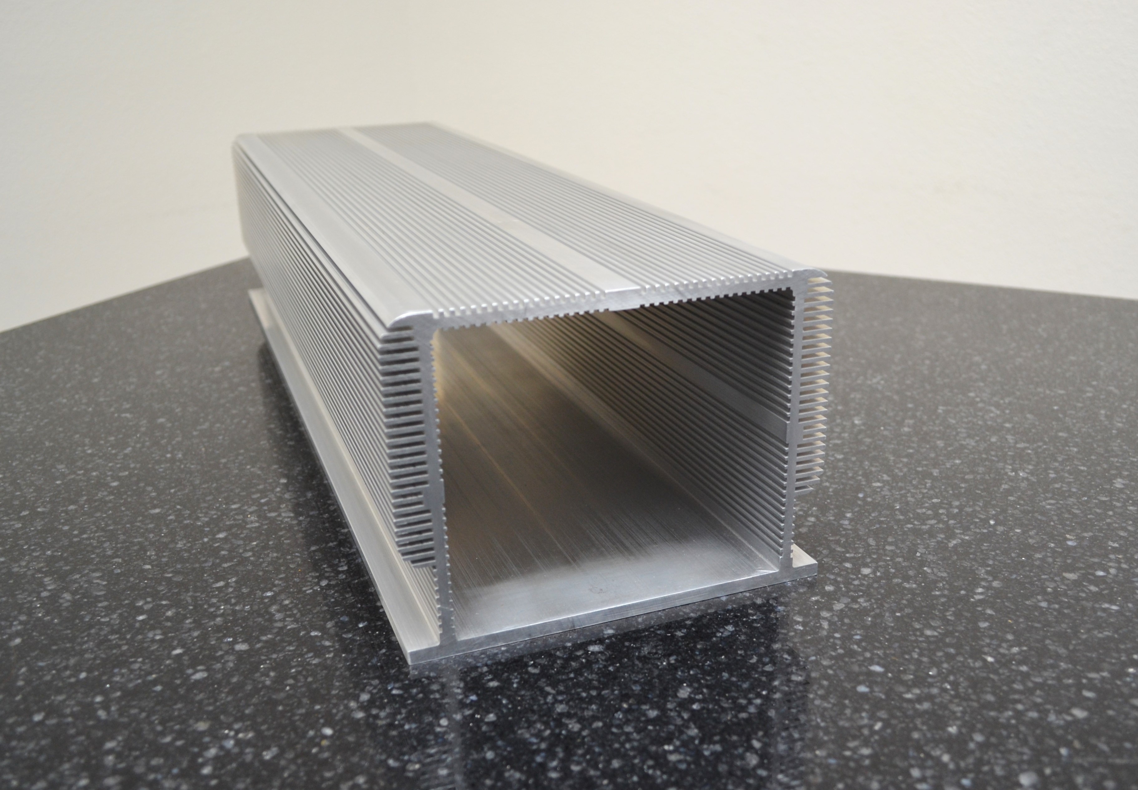
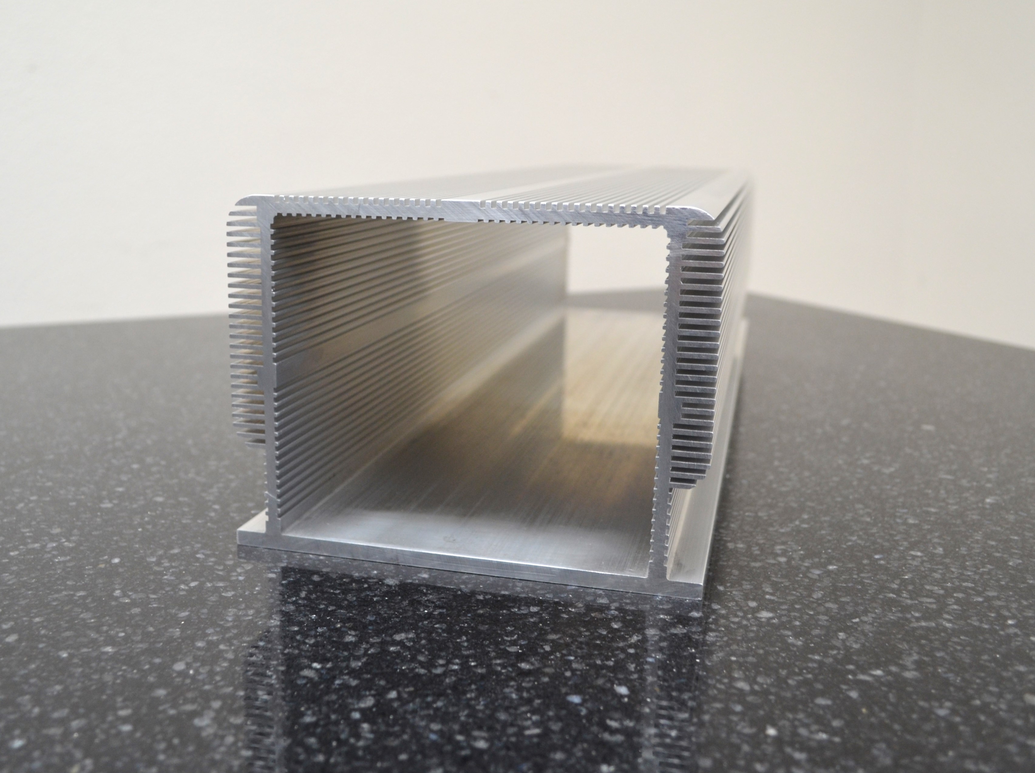
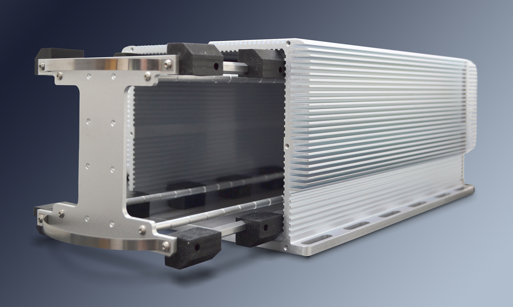
Perspective View of Chassis.
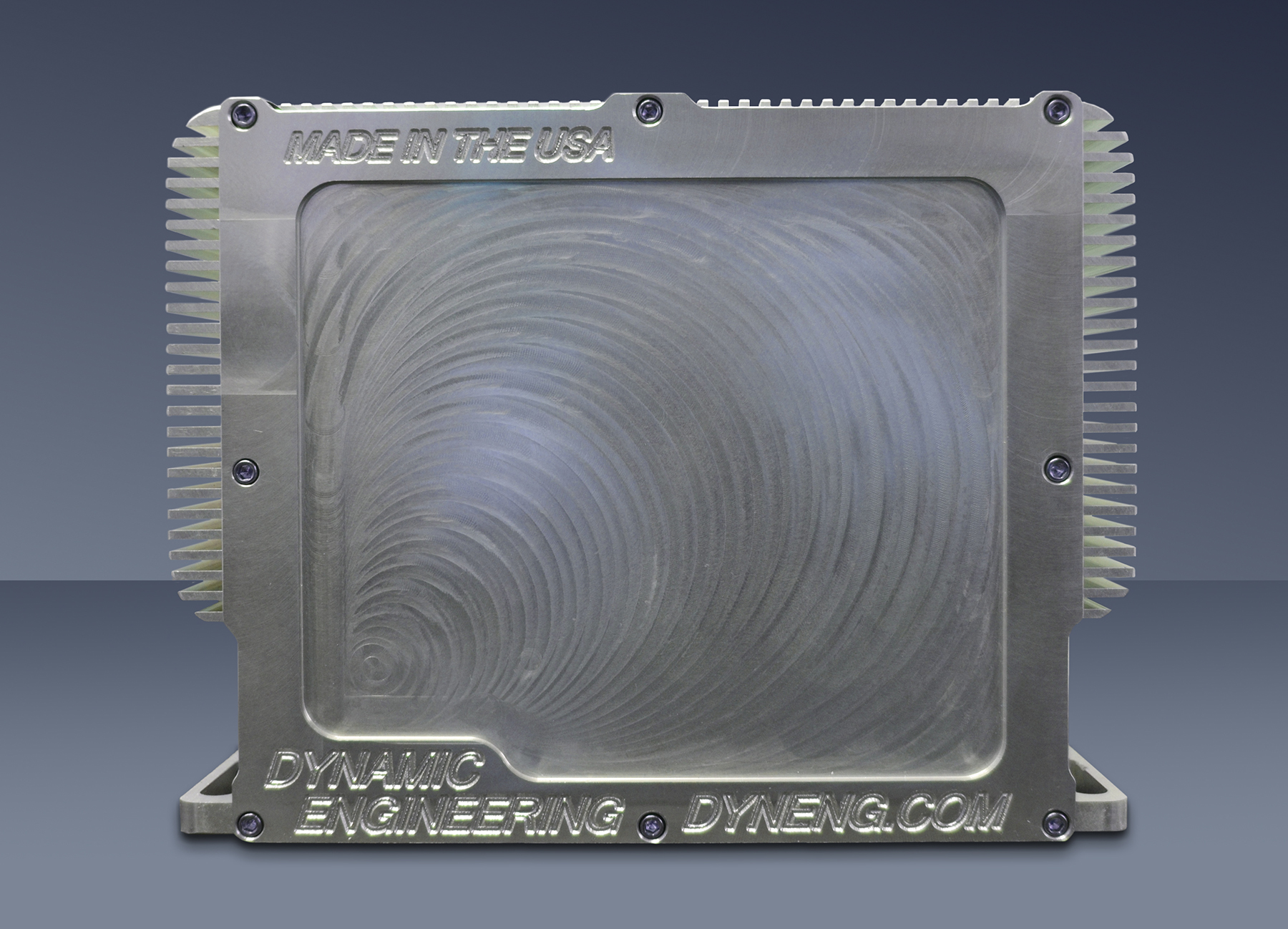
Angled view of current chassis. Shown with installed PC104p boards and single position SSD adapter.
Expand to full screen to see more detail.
To complete with the outer housing: slide the assembly into the outer housing and attach the remaining outer end plate [end cap]. The outer housing is designed to have gaskets and provide a sealed environment. The front and rear outer housing can be used to mount your system connectors. Dynamic Engineering can arrange to have custom cut-outs, and silk-screen or engraving for your chassis We can design connector plates to interface with cables. The end cap plates for the internal chassis are cut-out to allow for deeper connectors. One option is to use a smaller frame within a longer chassis to allow room for a hard drive or other custom applications. The chassis is designed to allow for air cooled operation as well as being conduction cooled. Fans can be mounted to the end cap and venting on the opposite.
The internal and external heat sink built into the chassis wall can allow internal air cooling too be used in a sealed environment. Internal air circulation with a sealed chassis is available with PC104p-COOL. With a fan card added to your stack the heat from your CPU etc. can be transferred to the sidewall and to the outside with the aide of the heatsinks. Spring steel provides a direct thermal path from the internal frame to the external chassis.
The internal hardware is rigidly mounted to the stack and shock / vibration isolated to the side wall with the bumper pads. The shorter boxes come with 8 bumper pads for the corners and the longer come with additional bumper pads.
Plenty of room is left for cabling along the sides of the chassis from the cards to the panel. The cable area is approximately 1 x 3.375 on each side of the chassis. The cable routing space coincides with the connector area of the PC104p to make it easy to install and secure the cables within the internal frame. With customized panel cut-outs you have have any IO you require.
The internal frame end plates are designed to allow for cabling and connector penetration from the chassis end cap.
The bottom plate comes with mounting slots to make it easy to attach to your system. The bottom plate can be used for additional cooling in a conductive cooling environment - cold plate attachment etc.
PC104p Chassis and enclosed stack will need power distribution. Any PC104 compatible supply can be used. PC104pPWR28 is recommended to convert from 28V [14-36] power rails to the +5, +3.3, +12, -12 and -5.5 you may need for your stack. PC104p-COOL card can be used to provide internal air-flow if your hardware has high power dissipation concentrated in a CPU etc. The "Cool" card has 2 fan positions, the fans can be oriented in either direction, and can be powered from either the PCI or PC104 rails. A fan board is a good addition for any high powered application to keep the power supply running cool. In addition the PC104p-RPP design provides reverse power protection for your power supply. The design uses FETs instead of diodes for a very small voltage drop. The connector placement and pin definitions are optimized to work with the PC104pPWR cards.
If you have custom requirements please call or e-mail us with the details.
email us your wish list or call today
The chassis incorporates an extruded aluminum outer housing with machined end caps. The interface between the End Cap and Chassis includes a gasket to support water tight operation at low pressures. The End caps are suitable for the addition of your connectors. The chassis is rugged and can work in a variety of environments.
The internal card cage is isolated with "bumper pads" from the external housing to provide vibration and shock absorption.
The chassis features heat sinks built into the external and internal walls. The current version has expanded heat sinks with larger wider fins compared to the original design. The internal heat sink has the added benefit of helping the internal chassis slide into position. The bottom surface is extended to create a mounting flange which can also be used for cooling in conductively cooled systems. The heat sink is tapered to provide access to the mounting flange. The heat sink is rounded to help avoid sharp edges.
Standard and custom lengths, power supplies, Fan boards, Reverse Power Protection, custom machining, surface finish, and etching or silk screening are available options. The shelf system is available to allow for mounting multiple SSD and/or other non-Stack HW to your system. In addition, a single slot SSD specific mounting adapter is available.
The PCIe104, PCI-104, PC104p, PC104 Chassis comes in base sizes : 1-11 where the size refers to the number of stack elements available. [an extrusion is used for the main body of the chassis making any length up to 24 in. possible]. The models are adaptable to allow any number of slots to be used up to the maximum for the chassis length. For example, if you need extra room for long connectors, or bend radiius on stiff cabling order a longer chassis coupled with a shorter internal frame. For example, an 11 slot chassis with a 9 position internal card cage. For custom combinations please contact Dynamic Engineering.
In a typical system the first position in the stack is the power supply, the second the CPU and the rest IO or storage. With the range of cards available for PCI-104, PC104, PC104p and IP available most applications can be implemented with off-the-shelf hardware and a chassis. a href="PC104p-PWR28.html"> PC104PWR28 can make a good power supply for PCI-104, PC104 and PC104p stacks or stacks with mixed cards. The 28V refers to aircraft 28V power. This supply has a wide range of input voltage and regulated protected outputs. The chassis is flexible and works with any assortment of cards.
To use the chassis: First, build your stack with standard spacers etc. Second attach to the rear plate with spacers and screws. Third add spacers to the front side to fill in the unused positions and attach to the internal cage front bezel. Attach shelving system if in use. Four screws and 4 nuts for the stack plus 4 more screws for the side supports. "rapid assembly!" We can provide additional assembly and test services to install the power supply, CPU, IO etc. shipping a completed unit to you.
Click on play to see videos for disassembly/reassembly of the inner chassis and outer chassis. Click the box for full screen. ESC returns to standard page. Click the download button to watch on your local machine - use when your internet bandwidth is too low to properly support the video.
Side View of Chassis.
Perspective View of Chassis.
Angled view of current chassis. Shown with installed PC104p boards and single position SSD adapter.
Expand to full screen to see more detail.
To complete with the outer housing: slide the assembly into the outer housing and attach the remaining outer end plate [end cap]. The outer housing is designed to have gaskets and provide a sealed environment. The front and rear outer housing can be used to mount your system connectors. Dynamic Engineering can arrange to have custom cut-outs, and silk-screen or engraving for your chassis We can design connector plates to interface with cables. The end cap plates for the internal chassis are cut-out to allow for deeper connectors. One option is to use a smaller frame within a longer chassis to allow room for a hard drive or other custom applications. The chassis is designed to allow for air cooled operation as well as being conduction cooled. Fans can be mounted to the end cap and venting on the opposite.
The internal and external heat sink built into the chassis wall can allow internal air cooling too be used in a sealed environment. Internal air circulation with a sealed chassis is available with PC104p-COOL. With a fan card added to your stack the heat from your CPU etc. can be transferred to the sidewall and to the outside with the aide of the heatsinks. Spring steel provides a direct thermal path from the internal frame to the external chassis.
The internal hardware is rigidly mounted to the stack and shock / vibration isolated to the side wall with the bumper pads. The shorter boxes come with 8 bumper pads for the corners and the longer come with additional bumper pads.
Plenty of room is left for cabling along the sides of the chassis from the cards to the panel. The cable area is approximately 1 x 3.375 on each side of the chassis. The cable routing space coincides with the connector area of the PC104p to make it easy to install and secure the cables within the internal frame. With customized panel cut-outs you have have any IO you require.
The internal frame end plates are designed to allow for cabling and connector penetration from the chassis end cap.
The bottom plate comes with mounting slots to make it easy to attach to your system. The bottom plate can be used for additional cooling in a conductive cooling environment - cold plate attachment etc.
PC104p Chassis and enclosed stack will need power distribution. Any PC104 compatible supply can be used. PC104pPWR28 is recommended to convert from 28V [14-36] power rails to the +5, +3.3, +12, -12 and -5.5 you may need for your stack. PC104p-COOL card can be used to provide internal air-flow if your hardware has high power dissipation concentrated in a CPU etc. The "Cool" card has 2 fan positions, the fans can be oriented in either direction, and can be powered from either the PCI or PC104 rails. A fan board is a good addition for any high powered application to keep the power supply running cool. In addition the PC104p-RPP design provides reverse power protection for your power supply. The design uses FETs instead of diodes for a very small voltage drop. The connector placement and pin definitions are optimized to work with the PC104pPWR cards.
If you have custom requirements please call or e-mail us with the details.
email us your wish list or call today
PCIe104, PCI-104, PC104p, PC104 Chassis Features
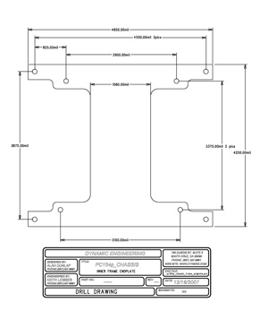
Dimensions
External Dimensions outer housing: 6.050” [top] x 5.3000” [side height] x length based on slot count. 7.050” [bottom with mounting flange]
Stack Height
Standard PCI-104, PC104p, PC104 cards - up to slot count number of modules. Modules for 3-11, or custom available. Larger units can be used with fewer cards and additional spacers if desired. Shorter units for 1, 2 cards can be manufactured for space constrained applications. Remember to count bank slots where double high modules are mounted or for extra airspace if a fan is used.
Weight
Empty weight of chassis including internal housing and no cards: 5 lbs. for 5-slot model, 6 lbs. for 7-slot model, 7 lbs. for 11-slot model.
Material
Outer chassis extrusion: Aluminum 6061
Outer chassis cap: Aluminum 6061
Hardware: Stainless
Inner chassis supports: Aluminum 6061 1/4 hex
Inner chassis end plates: Aluminum 6061
Bumper pads: 60 Durometer Black Silicone Rubber
Outer chassis cap: Aluminum 6061
Hardware: Stainless
Inner chassis supports: Aluminum 6061 1/4 hex
Inner chassis end plates: Aluminum 6061
Bumper pads: 60 Durometer Black Silicone Rubber
Thermal
Built in heat sink on side and top wall internal and external. Spring steel end supports tied into the card mounts to allow for direct heat conduction from the stack to the frame for passively cooled systems. Spring steel not shown in photos. Four locations at each end for even pressure and maximum conduction. Tie your ground plane to the mounting holes ot take advantage. Option for air cooled end plates with fans mounted. The PC104pPWR design has fused FAN power points to support this option.
PCIe104, PCI-104, PC104p, PC104 Chassis Benefits
Price
The Chassis is cost effective and ready to use. Just install your cards and customize the front panel. Low system cost due to easy installation, easy to achieve cooling requirements, and reliability keep your installed price low. Please email or call Dynamic Engineering for a quote. If you need custom machining done, please provide the requirements. Storefront prices are for standard configuration chassis. Quantity discounts are available.
Warranty
1‐year standard warranty. Extended warranties available.
Ease of Use
The Chassis is easy to use. The basic PC104 stack is assembled with the inner frame and then installed into the outer housing. The basic price includes the housing, frame, bumper pads, gaskets, and screws. Just add your hardware for a complete chassis. Custom machining and cable assemblies can be created. Dynamic Engineering can provide the assembly and provide a turn key solution.
Availability
We keep the extrusion and other components in stock. Due to the number of options we finish the chassis to order. Custom machining and marking may add to the lead time.
Size
Complies with standard PCIe104, PCI‐104, PC104p, and PC104 dimensions
PC104(p) Compatibility
PC104p Chassis is PCIe104, PCI-104, PC104, and PC104p compliant per specifications
Part Number: PCIe104, PCI-104, PC104p, and PC104 Chassis Ordering Options
-
Standard lengths shown. Other lengths available. Standard finish is raw metal. Options to coat with Black Anaodize, Surtec etc.
- PC104pChassis-2: Standard PC104p Chassis with 2 slots for 1-2 modules
- PC104pChassis-3: Standard PC104p Chassis with 3 slots for 1-3 modules
- PC104pChassis-4: Standard PC104p Chassis with 4 slots for 1-4 modules
- PC104pChassis-5: Standard PC104p Chassis with 5 slots for 1-5 modules
- PC104pChassis-6: Standard PC104p Chassis with 6 slots for 1-6 modules
- PC104pChassis-7: Standard PC104p Chassis with 7 slots for 1-7 modules
- PC104pChassis-8: Standard PC104p Chassis with 8 slots for 1-8 modules
- PC104pChassis-9: Standard PC104p Chassis with 9 slots for 1-9 modules
- PC104pChassis-10: Standard PC104p Chassis with 10 slots for 1-10 modules
- PC104pChassis-11: Standard PC104p Chassis with 11 slots for 1-11 modules
- SSDM Mount SSD within the PC104p stack. Requires 1 stack position. 2.5 in. SSD. Mount vertical or horizontal
Finish Options:
-ANT1CND:......Anodized Type I Chromic Non-Dyed (grey)
-ANT1C:...........Anodized Type I Chromic Dyed
-ANT2SND:......Anodized Type II Sulfuric Non-Dyed
-ANT2S:...........Anodized Type II Sulfuric Dyed
-ANT3ND:........Anodized Type III Hard Coat Non-Dyed
-ANT3:.............Anodized Type III Hard Coat Dyed
Add BLK(black), BLU(blue), BRN(brown), M(magenta), R(red), GRN(green), Y(yellow), O(orange) to dyed versions to pick your color e.g. "-ANT1CBLU" for a blue color.
-CF1ACL:......Chemical Film Class 1A Clear (Hexavalent)
-CF1AAU:......Chemical Film Class 1A Gold (Hexavalent)
-CF3HCL:......Chemical Film Class 3 Clear (Hexavalent)
-CF3TCL:......Chemical Film Class 3 Clear (Trivalent)
-NCD003:......Nickel Cadmium Diffused .0002-.0004 Ni, .0001-.0003 Cad, Color Gold
-CPT1D:........Cadmium Plate Type I Dull (no chromate)
-CPT1B:........Cadmium Plate Type I Bright (no chromate)
-CPT2CL:......Cadmium Plate Type II Clear (chromate)
-CPT2AU:......Cadmium Plate Type II Gold (chromate)
-CPT2OD:......Cadmium Plate Type II Olive Drab (chromate)
-NPC1A..E:......Nickel Plate Class 1 Grade (Pick A,B,C,D,E)
-ENC1..4:.......Electroless Nickel Class (Pick 1,2,3,4)
-ZPT1:...........Zinc Plate Type I (no chromate)
-ZPT2AU:......Zinc Plate Type II Gold Color (chromate)
-ZPT2OD:......Zinc Plate Type II Olive Drab Color (chromate)
-ZPT3CB:......Zinc Plate Type III Clear Blue (colorless chromate)
-ZPT3/5:........Zinc Plate Type III or V (colorless Trivalent Chromate)
-ZNT1:..........Zinc Nickel Type I (chromate as plated)
-ZNT2 :.........Zinc Nickel Type II (Chromate) Gold color
Accessories
Please contact Dynamic Engineering for spare parts.
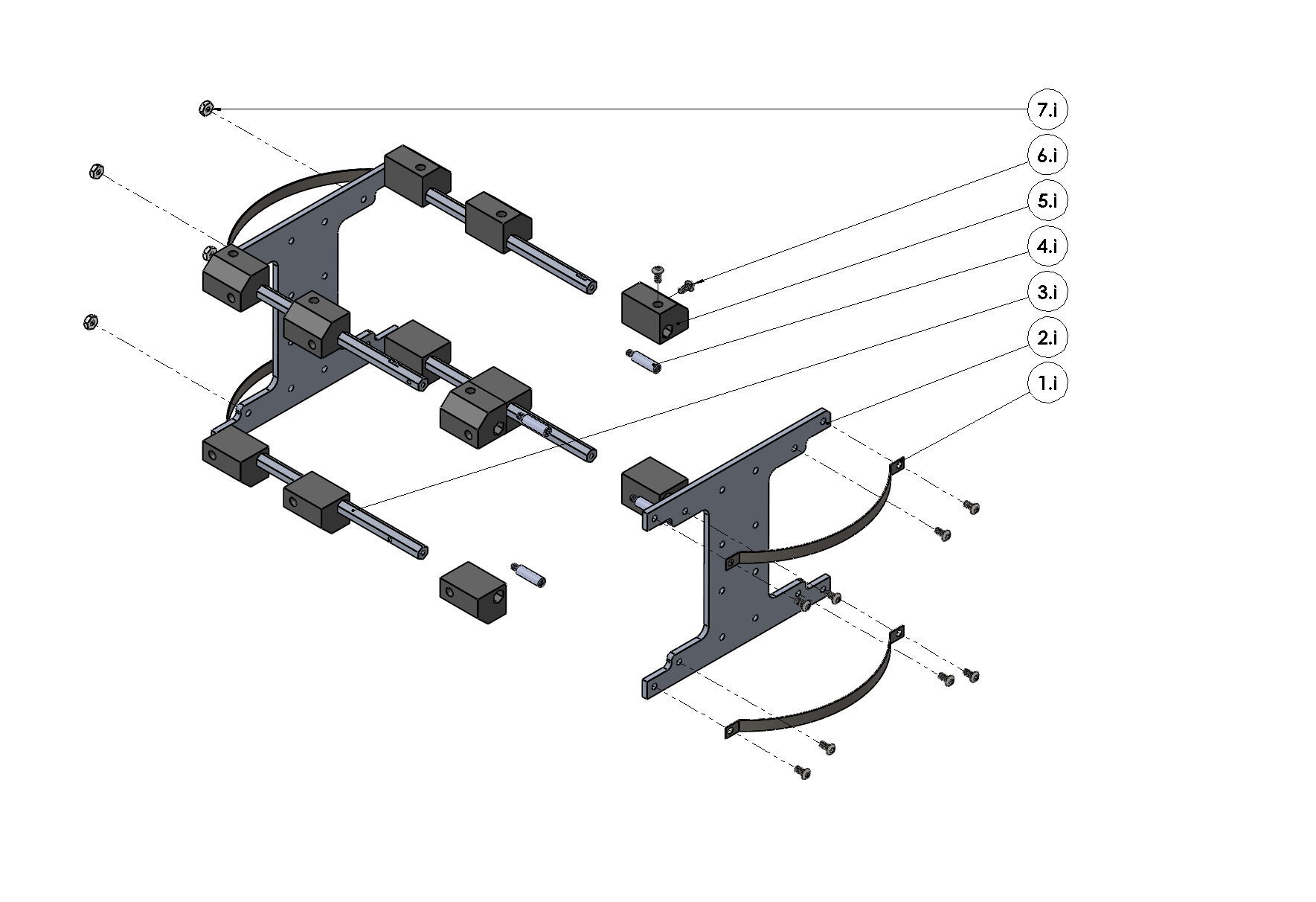
Item Number
Name
Dynamic Engineering
National Stock Number
1I
Thermal Spring
78-2008-1002
5340-01-727-1863
2I
Inner End Plate
76-2008-1006
3I
Inner Post
75-2008-1001-(02-15)
4I
4-40 M/F .6 Stand Off
91075A433 or eq.
5I
Bumper
73-2008-1002
6I
Hex Socket 4-40x.25
9816A061 or eq.
7I
4-40 Hex Nut
MS35649-244 or eq.
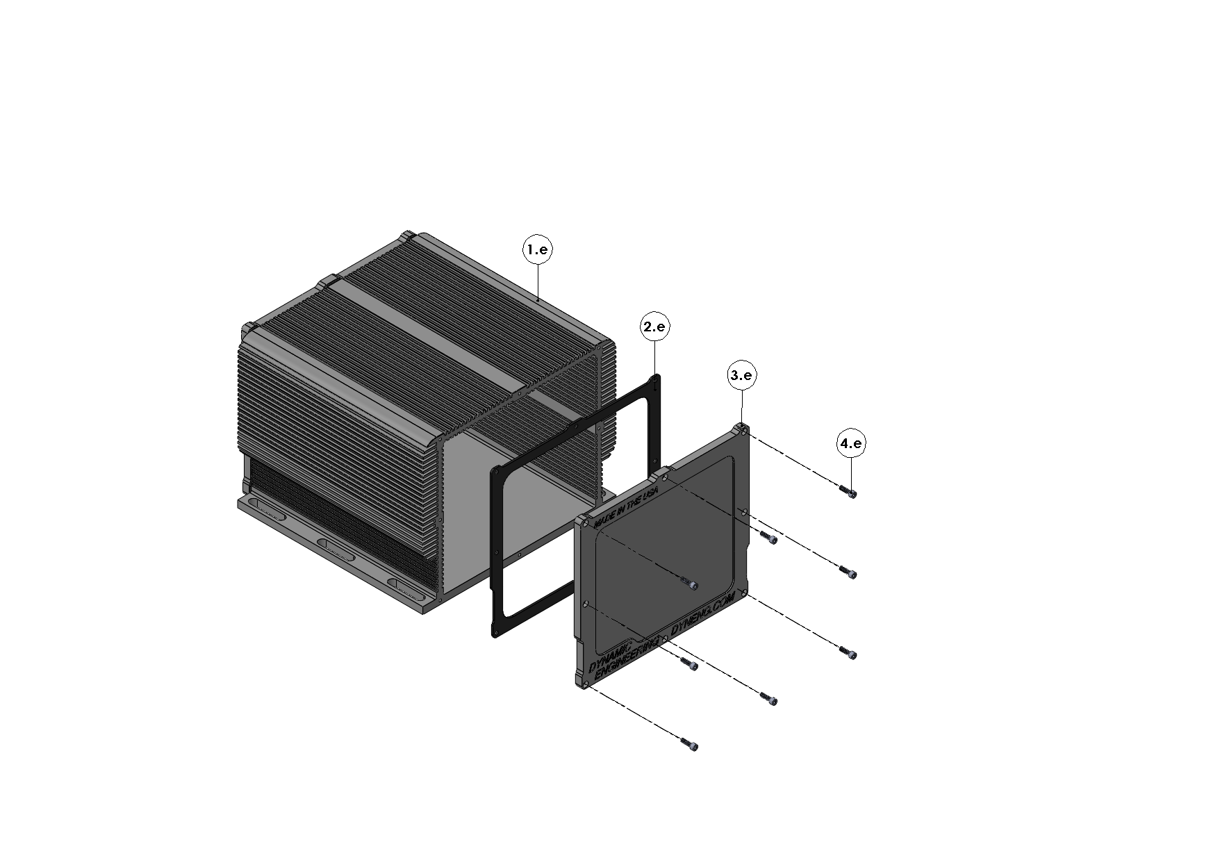
Item Number
Name
Dynamic Engineering
National Stock Number
1E
External Chassis
70-2008-1003-(02-15)
2E
Gasket
77-2008-1003
3E
Outer End Plate
71-2008-1003
4E
Socket Hex 4-40x.375 or eq.
91251A108